What Is CNC Parts Machining and How Does It Work?

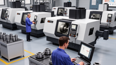
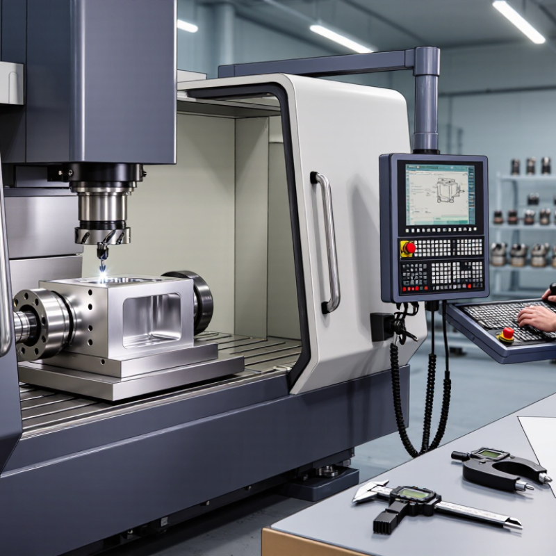
CNC Parts Machining turns a digital design into a physical component through controlled cutting. A machinist loads a workpiece—perhaps an aluminum block or steel bar—into a CNC mill or lathe. The machine then follows programmed instructions to remove material with precision. The result can be a simple spacer or a complex housing with pockets, holes, and carefully finished surfaces.

Manufacturing engineer Alex Morgan puts the shop-floor principle this way: “A precise part starts with a sound setup, not just a good program.” This is a useful reminder, though it should not replace a verified, published quotation. Tool choice, workholding, cutting speed, and material all affect the result. A small setup error can leave a visible mark or push a dimension out of tolerance. The process is automated, but judgment still matters.

This guide explains what Cnc Parts Machining means and how its main steps connect, from CAD design and CAM toolpaths to cutting, inspection, and finishing. You will see where milling and turning differ, what tolerances mean in practice, and why machinists check parts with tools such as calipers and micrometers. CNC is not magic. Nor is every part easy to make. A drawing may look clean on screen, yet a thin wall can vibrate under a cutter. That detail deserves a second look. Understanding the process helps engineers choose sensible designs, compare manufacturing options, and ask clearer questions before production begins.
What Is CNC Parts Machining and How Does It Work?

What CNC Parts Machining Means

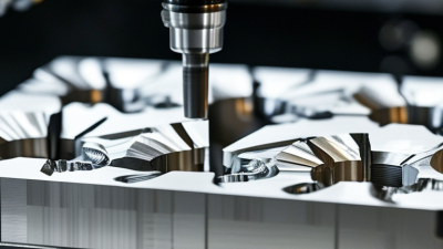
CNC parts machining is the controlled removal of material from a solid workpiece using computer-guided tools. A designer creates a digital model, then software turns its geometry into toolpaths and machine instructions. The machine moves a cutter along programmed coordinates while the workpiece is held firmly in place. Metal chips curl beside the vise; each pass brings the surface closer to its specified shape. That is the basic idea. CNC machining can include milling, turning, and drilling, with each process suited to different features. The term describes both the digital control and the physical cutting—not a guarantee that every part will be identical.

In practice, results depend on more than the program. Tool wear, material variation, clamping pressure, and temperature can all affect dimensions. A machinist checks critical features with tools such as micrometers or coordinate-measuring equipment, then adjusts the setup when readings drift. Small holes and thin walls can be especially unforgiving. A clean simulation may still miss a real-world issue. The setup is easy to underestimate. Industry scale offers useful context: Grand View Research’s CNC Machine Market report estimated the market at USD 101.22 billion in 2023 and projected a 9.5% compound annual growth rate from 2024 to 2030. That figure describes the market, not machining accuracy, but it reflects the process’s broad industrial role.

What Is CNC Parts Machining and How Does It Work? - What CNC Parts Machining Means
Topic What It Means How It Works or Typical Examples
CNC parts machining A manufacturing process in which computer-controlled machine tools remove material from a workpiece to create a part. The machine follows programmed instructions to move cutting tools and, where applicable, the workpiece along specified paths.
Program and toolpath A digital part design is translated into machine instructions, commonly using computer-aided manufacturing (CAM) software. The program defines movements, cutting operations, tool changes, and other machine actions. G-code is a widely used format for CNC instructions.
Workholding and setup The stock material is secured, and the machine is prepared with the required tools and reference positions. Stock may be held in a vise, chuck, or fixture. The operator sets work offsets and verifies that the tools and setup match the program.
CNC milling A rotating cutting tool removes material from a stationary or repositioned workpiece. Common milling operations include creating flat surfaces, slots, pockets, and drilled features. Three-axis machines move along X, Y, and Z; multi-axis machines add rotational movement.
CNC turning The workpiece rotates while a cutting tool removes material from its surface. Turning is commonly used for cylindrical parts and features such as outside diameters, bores, grooves, and threads.
Materials and stock The starting workpiece, often called stock, is selected to suit the part’s design and application. Common machinable materials include aluminum, steel, stainless steel, brass, and engineering plastics. Material choice affects cutting tools, speeds, and finishing requirements.
Machining and inspection The machine executes the program, and the finished features are checked against the part drawing or model. Measurements may be made with instruments such as calipers, micrometers, gauges, or coordinate-measuring equipment. Achievable tolerances depend on the material, geometry, machine, tooling, and setup.
Finished part The machined component may be ready for use or may require additional finishing. Depending on the design, follow-up work can include deburring, surface finishing, heat treatment, or cleaning.

Key Machines, Tools, and Materials

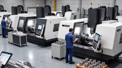
CNC parts machining uses programmed toolpaths to remove material from a secured workpiece. A three-axis milling machine cuts flat faces, pockets, and holes; four- and five-axis machines reach angled surfaces with fewer setups. CNC lathes rotate round stock while turning tools shape its diameter. Mill-turn machines combine both operations. Common cutting tools include carbide end mills, drills, and replaceable inserts. A probe can check dimensions during a cycle, but it cannot fix a poorly clamped part. Small details matter.

Material choice changes the whole process. Aluminum cuts quickly, while stainless steel often needs slower cutting and steady coolant to limit heat. Steel remains widely available: World Steel Association’s World Steel in Figures 2024 reports 1.89 billion tonnes of crude steel production in 2023. Copper alloys suit conductive parts, though they can form long, troublesome chips. USGS Mineral Commodity Summaries 2024 estimates 22 million tonnes of global copper mine production in 2023.

Those figures describe supply, not machinability; alloy grade and condition still matter. A shop can still get this wrong. Thin walls may vibrate under a sharp tool, leaving chatter marks and uneven dimensions. Machinists therefore balance tool geometry, cutting speed, workholding, and inspection against the drawing’s tolerances. A practical setup often starts with a test cut.

How a Part Design Becomes CNC Instructions

A CNC-machined part begins as a digital design, often created in CAD software. The model defines surfaces, holes, slots, and dimensions. It should also specify tolerances and material. A 10-millimeter hole with a tight tolerance may need a different cutting strategy than a clearance hole. Small details matter.

The CAD model is then prepared in CAM software. A programmer chooses the raw stock, machine setup, cutting tools, and machining sequence. For example, a flat face may be milled before smaller pockets are cut. The software converts these choices into toolpaths: planned movements that guide each cutter around the part. Cutting speed, feed rate, and tool depth affect both finish and tool wear. These settings depend on the material and machine, so copying values without checking them can cause trouble.

The CAM system generates machine instructions, often called G-code, through a postprocessor suited to the machine’s controls. Before cutting metal, the programmer can simulate the toolpaths to spot collisions, missed features, or excessive material removal. Still, a simulation is not proof that every setup detail is correct. The workpiece must be secured, tools measured, and the program checked at the machine. A careful first run may use reduced speed. It takes time. But that check can reveal a fixture offset or tool length error that the screen did not make obvious.

What Is CNC Parts Machining and How Does It Work?

This example shows how a 20 mm × 20 mm square part design can be translated into CNC toolpath coordinates. CAD defines the geometry, CAM generates the toolpath, and the resulting coordinates are converted into machine instructions.

Each waypoint represents a position along the square’s perimeter. These X and Y coordinates are example values in millimeters; a real CNC program also specifies details such as tool movement, feed rate, and spindle speed.

How CNC Machines Shape a Part Step by Step

A CNC-machined part begins as a digital model and a piece of stock, such as aluminum bar or plastic sheet. An engineer checks the model’s dimensions, tolerances, and surfaces, then selects a mill, lathe, or other suitable machine.

Small details matter. A thin wall may need extra support to prevent vibration or distortion during cutting.

The model is translated into toolpaths that guide the cutting tool through the material. The operator secures the stock in a vise or fixture, loads the tools, and sets the workpiece origin. A probe can help locate the stock precisely.

The machine then removes material in stages: roughing cuts clear most of the excess, while finishing passes create the specified edges and surfaces. Coolant may reduce heat and carry chips away.

The first setup is not always perfect.

During machining, the operator watches for unusual sounds, tool wear, or built-up chips. These can affect dimensions or leave a rough finish.

After cutting, the part is measured with instruments such as calipers, micrometers, or a coordinate measuring machine. If a feature is out of tolerance, the cause may be tool deflection, setup error, or a mistaken assumption in the model.

One detail is easy to overlook: a drawing can specify a dimension, but the chosen inspection method must still measure it reliably.

How Finished Parts Are Measured and Verified

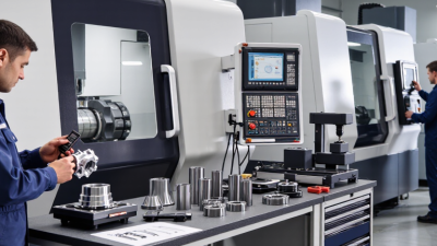
After CNC machining, verification starts with the drawing, not the measuring tool. The inspector identifies critical dimensions, datums, and specified tolerances, then selects suitable equipment. A micrometer can check a shaft diameter; a bore gauge can reveal a hole’s size and taper. For complex features, a coordinate-measuring machine probes several points against the part’s datums. Surfaces must be clean, and temperature matters: a warm metal part can measure differently from one near room temperature. Small details count.

Measurement results also need context. NIST Technical Note 1297 explains that expanded uncertainty is calculated using a coverage factor; a factor of 2 corresponds to approximately 95% coverage under stated assumptions. Consider a 20.00 ± 0.05 mm feature. If the measurement’s expanded uncertainty is 0.01 mm, that equals 10% of the full 0.10 mm tolerance band. A result near either limit deserves care, not an automatic pass. The inspector may repeat the measurement, check calibration status, or use a more suitable instrument. Record the readings, method, and conditions. A clean number can still be wrong. Measurement setup is not always perfect, and that uncertainty should be acknowledged.

Certified Quality System

© North Easton Machine Company, Inc. All rights reserved. • Site: Blog
NORTH EASTON MACHINE • 218 Elm Street • North Easton, MA 02356 • 508-238-6219