Top 10 CNC Milling Axis Types Buyers Should Know?
Choosing a Cnc Milling Axis configuration affects part access, setup time, tooling, and the machine’s purchase cost. A three-axis mill can handle many flat faces and pockets efficiently. Add rotary axes, and the cutter can reach angled surfaces or machine several sides with fewer repositioning steps. More movement is not automatically better. Extra capability can also mean greater programming demands and maintenance.
CNC applications engineer Alex Morgan puts the trade-off this way: “More axes do not guarantee better parts; they expand how the tool can reach and orient the work.” Treat that as a practical rule of thumb, not a substitute for checking the part, tolerance, and production volume. A deep impeller, a medical housing, and a simple aluminum bracket do not need the same motion.
This guide compares the 3-, 4-, 5-, and other axis arrangements buyers may encounter. It explains what each axis adds, where it earns its cost, and what to verify before requesting a quote. Look closely at rotary travel, workholding, control options, and operator skill. Details matter. Axis labels can also be confusing between machine builders, so confirm what moves—the spindle, table, or both. A small caveat, but an important one.
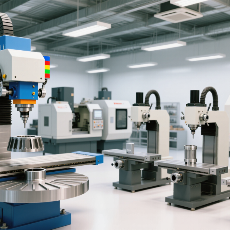
Define CNC Milling Axes: X/Y/Z Linear and A/B/C Rotary (ISO 841)
CNC milling axes describe how the tool or workpiece moves. ISO 841:2001 assigns X, Y, and Z to the principal linear axes, and A, B, and C to rotary axes around those directions. That gives six primary axis labels. It is a coordinate convention, not a guarantee that every machine can move all six axes simultaneously.
On a typical vertical mill, X moves the table left and right, Y moves it forward and back, and Z moves the spindle up and down. A rotates around X; B rotates around Y; C rotates around Z. Picture a cutter tracing a flat pocket in X and Y, then lowering into the material along Z. Add a rotary axis, and the setup can tilt or turn the part to reach angled faces. ISO 841 defines the naming framework; machine layouts may assign motion to the tool, the table, or both.
Axis count alone can mislead buyers. A five-axis machine does not necessarily offer the same reach or simultaneous motion as another five-axis design. Check the machine’s kinematic diagram, rotary travel, and control specifications. The labels sound tidy. Real setups are less tidy, especially when fixtures block access. ISO 841 is the authoritative reference for axis nomenclature; the machine builder’s technical documentation should confirm actual travel and capabilities.
Compare Three-Axis Mills with A-, B-, or C-Rotary Four-Axis Mills
A three-axis mill moves the cutting tool along X, Y, and Z. It suits flat parts, open pockets, and many prismatic components. For a plate with drilled holes on one face, a three-axis setup can be simple and economical. Setup is familiar. But machining several sides may require unclamping and repositioning the part, which can add time and alignment error.
A rotary fourth axis lets the workpiece turn while the tool cuts. An A-axis rotates around X, a B-axis around Y, and a C-axis around Z; the exact orientation depends on the machine design. A C-axis can suit shafts or cylindrical features, while A- or B-axis arrangements may help expose angled faces. Think of a machined block turning to present each side without manual removal. The extra motion can reduce setups, but it does not automatically improve every job. Fixture clearance, part shape, tool reach, and programming skill still matter. Not every job benefits. Compare expected setup savings with added fixture and programming demands before choosing a four-axis mill.
Five-Axis Designs: 3 Linear + 2 Rotary, from Trunnion to Swivel-Head
Five-axis milling uses three linear axes—X, Y, and Z—plus two rotary axes. The rotary pair tilts the tool or workpiece, allowing the cutter to reach several faces with fewer setups. Axis labels vary by machine, so buyers should confirm which motions rotate around which directions. Small detail, big consequence.
A trunnion design tilts and rotates the table beneath a mostly fixed spindle head. It can provide compact access to multiple sides, but the table’s load capacity and travel may limit part size. A swivel-head design moves the spindle instead, which can suit larger workpieces. Yet its head geometry may affect reach and collision clearance. Hybrid layouts combine moving-table and moving-head motions.
Ask for examples using parts similar to yours. Check rotary travel, table capacity, tool length, and clearance around fixtures; a five-axis specification alone says little about usable access. Simultaneous motion can reduce repositioning, but it also demands suitable programming, calibration, and operator skill. That part gets overlooked. I would compare the machine’s working envelope under rotation, not just its advertised X, Y, and Z travels. A beautifully accessible setup on paper can still be awkward with a real vise, long tool, or bulky casting.
Explore Six-, Seven-, and Higher-Axis Mills, Including Mill-Turn Designs
Six-axis and seven-axis mills extend the familiar three linear axes with added rotary or swiveling motion. On a six-axis machine, three rotary axes can orient a cutter around a part, though the exact layout varies. A seven-axis design may add another rotary or linear movement. That extra motion can reach awkward surfaces, such as angled ports inside a cast housing, with fewer repositioning steps.
Mill-turn machines combine rotating workholding with milling capability. Their axis count depends on the spindle arrangement and available movements, so compare machine specifications rather than relying on the label. A subspindle or Y-axis can help machine more features in one setup. Still, more axes mean more programming, collision checks, and operator training. The terminology can be messy, and extra motion does not automatically improve a part.
Tips: Ask for a sample cycle using your part geometry. Check tool access, setup count, and inspection needs. A simpler machine may be the better fit.
Assess Axis Accuracy and Repeatability with ISO 230-2 Tests
Top 10 CNC Milling Axis Types Buyers Should Know?
Assess Axis Accuracy and Repeatability with ISO 230-2 Tests
Axis count alone does not reveal machining precision. Buyers should examine measured positioning accuracy and repeatability for each linear or rotary axis. ISO 230-2:2014 specifies methods for testing numerically controlled axes and reporting positioning deviations. A useful test report identifies the axis, measurement direction, target positions, and test conditions. Small details matter. Temperature drift or inconsistent probing can distort results.
Consider a clearly labelled example: a 300 mm linear axis shows 8 μm bidirectional positioning deviation and 3 μm repeatability. These figures are illustrative, not ISO limits or a machine rating. Buyers should compare actual reports, not catalogue claims, and confirm that test conditions match their intended use. A rotary axis deserves the same scrutiny, especially when contouring depends on coordinated motion. Ask whether results include both travel directions and repeated measurements. One test is not enough. ISO 230-2 gives a shared measurement framework, but it cannot predict every shop-floor outcome; fixture rigidity, tool loading, and thermal changes still matter. That gap deserves attention.
Top 10 CNC Milling Axis Configurations Buyers Should Know
Examples of common linear and rotary axis combinations. Bars show the number of linear and rotary axes—not accuracy rankings.
Accuracy and repeatability: Axis count alone does not indicate machining precision. ISO 230-2 tests assess the positioning accuracy and repeatability of an individual numerically controlled axis; results must come from measurements on the machine being evaluated.




 Find Your Solutions ▶