
What Is a Transformer Core Cutting Line?
A Transformer Core Cutting Line is an integrated production system for converting electrical steel coils into precise laminations. These laminations form the magnetic core inside distribution and power transformers. The line usually combines decoiling, feeding, measuring, cutting, stacking, and scrap collection equipment. Its purpose is not simply to cut metal. It must protect magnetic performance while maintaining stable dimensions.
In practical production, grain-oriented electrical steel passes through guided rollers before high-speed blades create mitred or step-lap joints. A small cutting error can increase assembly gaps, noise, and no-load losses. Operators therefore monitor blade condition, strip tension, burr height, stacking alignment, and insulation coating damage. Experienced technicians also compare actual measurements with drawings and approved process limits. Modern equipment may include servo drives, automatic length control, laser positioning, and data recording. These features improve repeatability, but they do not remove the need for human judgment.
No line is perfect. Material variation, worn tooling, or poor calibration can still affect results. That is easy to underestimate. A reliable manufacturer validates cutting accuracy through routine inspections, trial runs, and documented maintenance. Engineers should also consider transformer size, steel grade, joint design, production volume, and factory space before selecting equipment. Safety guarding and controlled access remain essential around moving coils and cutting tools. This guide explains how a Transformer Core Cutting Line works, which components influence quality, and why careful process control matters. Some details vary between suppliers, so technical claims should be checked against equipment specifications, standards, and verified production records.
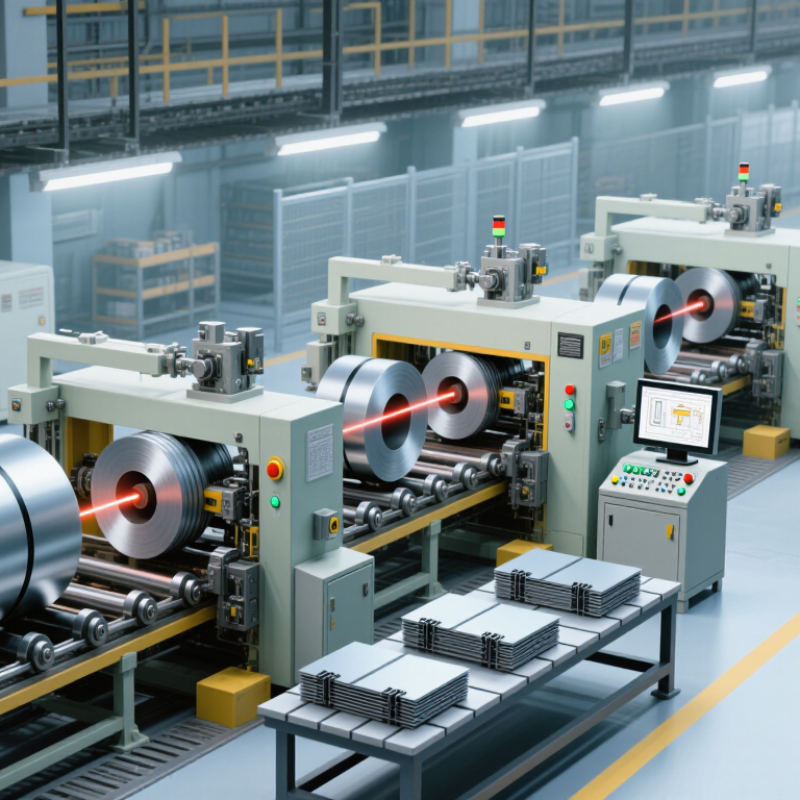
Definition and Purpose of a Transformer Core Cutting Line
A transformer core cutting line is an integrated production system for preparing electrical steel sheets. It cuts, trims, and stacks thin strips into accurate core sections. These sections guide magnetic flux inside a transformer. The main purpose is to reduce energy loss, improve core assembly, and support stable transformer performance. By controlling strip length, angle, and alignment, the line creates repeatable shapes for different core designs. In practice, even a small cutting error can affect the final assembly.
A typical line includes a decoiler, feeding unit, precision shear, scrap collection system, and stacking equipment. Sensors monitor position and movement during operation. Accurate cutting reduces burrs and limits unwanted gaps between steel pieces. This matters. Gaps can increase noise, vibration, and magnetic losses. Experienced technicians still need to check blade condition, material tension, and stacking quality. No machine removes every risk. Settings may work well today but require adjustment tomorrow.
Tips: Inspect cut edges under good lighting before production continues. Keep the feeding path clean and free from loose steel fragments. Record key settings for each material thickness. Do not judge quality by speed alone. A clean edge helps. Small errors accumulate. Reviewing actual results remains essential, because production conditions are rarely perfect.

Materials and Components Used in Core Production
What Is a Transformer Core Cutting Line?
Materials and Components Used in Core Production
A transformer core cutting line processes electrical steel into precise laminations. The usual material is grain-oriented electrical steel, often supplied in coils. Its thin sheets reduce eddy-current losses inside the finished core. An insulating coating separates adjacent laminations and limits unwanted current flow. Clean edges matter. Oil, dust, and moisture can damage surface quality, so storage conditions require careful control.
The line begins with a decoiler, which holds and releases the steel coil. A straightening unit removes coil memory before cutting begins. Slitting knives may divide wide material into narrower strips. Servo-driven feeders then control length and position.
High-speed shears create mitred, step-lap, or rectangular laminations. A stacking table collects each piece in a programmed sequence. Sensors check alignment, sheet presence, and possible feeding errors. Small errors multiply.
In practical production, operators also inspect burr height, corner angles, and coating damage. Excessive burrs can increase losses and create poor contact between layers. The control system records dimensions and production settings for traceability.
A stable cutting line needs rigid frames, accurate guides, reliable drives, and properly maintained blades. It sounds simple. Yet material tension changes during a coil, and even experienced technicians may need to adjust speed or pressure.
Not always.
A perfect setting for one steel grade may perform poorly with another thickness, so trial data and regular measurement remain essential.
Main Cutting Processes and Equipment
A transformer core cutting line converts electrical steel coils into accurately shaped laminations for transformer assembly. The line usually begins with a decoiler, which releases the coil under controlled tension. A leveling unit removes coil memory and keeps the strip stable during feeding. This step matters because uneven tension can create waviness, inaccurate dimensions, and stacking problems.
The main cutting processes include longitudinal slitting, cross-cutting, V-notching, and corner cutting. Slitting creates the required strip widths. A precision shear then cuts laminations to programmed lengths. V-notching and corner cutting form the joint geometry used in step-lap core construction. Servo-driven feeding systems control movement before each cut. Sensors check strip position, while automatic scrap collection keeps the working area clear. Burr inspection is also important. Excessive burrs may damage insulation or increase losses between laminations.
Operators normally verify length, width, notch position, and edge quality with calibrated tools. They also inspect the first pieces after coil changes. In practice, alignment is never perfect. Small deviations can appear when material thickness, tension, or tool wear changes. This is where experienced adjustment helps. A well-designed line still needs human judgment. Sometimes, slower feeding produces better stacking accuracy than maximum speed. That trade-off is easy to overlook. Clean guides, sharp tooling, and recorded inspection results make the process more reliable over repeated production runs.
Step-by-Step Operation of the Production Line
What Is a Transformer Core Cutting Line?
Step-by-Step Operation of the Production Line
A transformer core cutting line converts grain-oriented electrical steel into precise magnetic core laminations. The process matters because core losses affect transformer efficiency. The U.S. Department of Energy estimates that distribution transformers consume about 2.5% of total U.S. electricity use. The IEA’s Electricity 2024 report also expects global electricity demand to grow strongly through 2026. Better core manufacturing is becoming less optional.
The operation starts with coil loading and controlled decoiling. Operators check strip width, surface condition, and material direction. The line then slits or cuts the steel into programmed lengths. High-speed blades create step-lap joints, reducing magnetic resistance at the corners. Sensors monitor strip position during feeding. A small deviation can damage the final stack.
After cutting, each lamination moves to a collecting or stacking station. Operators arrange pieces according to the core design, often using an alternating overlap pattern. The stack is measured for height, squareness, and joint quality. Burr height receives careful attention because sharp edges can increase losses and damage insulation. Many lines use automatic vision inspection, but it is not perfectly reliable. I would not trust a clean-looking stack alone. Manual checks still matter, especially after tool changes or unusual noise. Final records should include material grade, dimensions, cutting speed, defect readings, and operator approval. That traceability supports consistent production and easier root-cause analysis.
Quality Control and Performance Considerations
What Is a Transformer Core Cutting Line?
Quality Control and Performance Considerations
A transformer core cutting line converts electrical steel coils into precise laminations. Its performance depends on cutting accuracy, stable feeding, and careful material handling. Even a small burr can increase assembly gaps and local losses. Operators should check blade condition, strip alignment, and cutting pressure during every production shift. These checks sound basic. They prevent expensive rework.
Quality control should begin with incoming steel inspection. Measure thickness, coating condition, width, and mechanical damage before loading the coil. During cutting, sensors can monitor length, angle, speed, and stacking position. Samples should be measured with calibrated tools, not visual judgment alone. A clean edge matters, but dimensional consistency matters more. Poor stacking can distort the finished core and create uneven clamping pressure.
Performance also depends on software settings and operator response. Cutting speed must match material grade, thickness, and equipment capacity. Excessive speed may reduce accuracy and increase burr formation. Low speed can reduce output without improving quality. Maintenance records should connect defects with specific settings, tools, and production times. This creates useful evidence for corrective action.
However, inspection systems are not perfect. Dust, vibration, and sensor drift can produce misleading readings. Periodic manual verification remains necessary, even in automated lines. A practical improvement is to review rejected laminations weekly and question repeated assumptions. Some defects may come from handling, not cutting.
NORTH EASTON MACHINE • 218 Elm Street • North Easton, MA 02356 • 508-238-6219