7 Tips for Buying Multi Pair Instrumentation Cable
Choosing the right Multi Pair Instrumentation Cable can protect a measurement signal from noise, reduce installation problems, and support dependable readings over time. The challenge is that cables with similar pair counts may differ in shielding, conductor size, insulation, and temperature ratings. A cable that looks suitable on a purchasing sheet may behave differently beside a variable-frequency drive or inside a crowded tray. Small details matter.
EMC engineer Henry W. Ott is often associated with this practical principle: “The best way to solve EMC problems is to prevent them from happening in the first place.” Applied to cable selection, that means considering the installation environment before a signal becomes unstable. Check whether each pair needs individual shielding, whether an overall shield is required, and how the cable will be grounded. Also confirm conductor size, capacitance, voltage rating, and compatibility with the instruments and terminals. Don’t assume “shielded” answers every question.
This guide presents seven useful checks for comparing cable options. It looks at signal type, pair construction, shielding, insulation, operating conditions, installation constraints, and supplier documentation. A close inspection of the specification sheet can reveal mismatches, such as a cable rated for a dry control room but planned for a damp process area. Ask for clear test data when a claim is vague. Even careful buyers can overlook one requirement. That deserves a second look. The right choice depends on the actual route and equipment, not just the product name.
Understanding Multi-Pair Instrumentation Cable and Its Applications
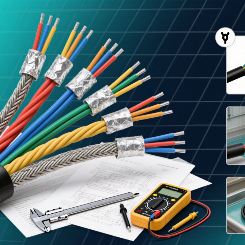
Multi-pair instrumentation cable carries several low-level signal circuits within one outer sheath. Each pair has two insulated conductors, often twisted to reduce electrical noise pickup. A foil or braid shield may surround each pair, the whole cable, or both. Small detail, big difference. Individual shields help limit crosstalk when nearby circuits carry different signals. An overall shield can add protection from external interference. Drain wires provide a practical path for grounding, but grounding methods should follow the system design.
These cables commonly connect pressure transmitters, temperature sensors, flow meters, and control-room panels. In a plant, one cable may route several instrument loops along a tray, reducing separate runs. Yet shared routing does not make every signal interchangeable. Check conductor size, pair count, insulation rating, capacitance, shielding arrangement, and permitted installation temperature against site requirements. A cable that looks robust may still be unsuitable for a long, sensitive signal run.
Before buying, map the actual circuit list and select a suitable pair count. Spare pairs can help with future changes, though excess capacity may add unnecessary cost. Consider moisture, oil exposure, vibration, and routes near power cables. Request construction details and test documentation, not just a general “instrumentation” label. Cable schedules can become confusing after field changes, so clear pair identification matters. Verify termination practices with the project engineer; a poorly grounded shield can weaken otherwise careful noise control.
Defining Pair Count, Conductor Size, and Electrical Requirements
Pair count should come from the instrument schedule, not guesswork. Count every signal that must run between field devices and the control room, then consider spare pairs for future changes or troubleshooting. A cable with too few pairs can force extra runs; too many pairs can increase cable diameter, weight, and termination time. Check the route and junction-box space before ordering.
Conductor size affects resistance and voltage drop. IEC 60228 lists maximum copper-conductor resistance at 20°C as 12.1 Ω/km for 1.5 mm² and 7.41 Ω/km for 2.5 mm² conductors. Longer runs and higher current make that difference more significant. For low-level instrument signals, also verify capacitance, insulation rating, shielding, and the instrument’s permitted loop resistance. Keep margin. A calculation based only on nominal distance may miss temperature, connections, and future extensions.
Match cable construction to the actual electrical and site requirements. Separate pairs can reduce crosstalk, while an overall shield may suit installations needing common noise protection; some applications need individual pair shields instead. Confirm grounding practice and compatibility with the connected instruments. IEC resistance figures are useful, but they do not settle every design choice. I would recheck the final selection against the instrument datasheets and measured route length, especially when several pairs share a crowded tray.
Evaluating Shielding, Insulation, and Cable Construction
Choosing multi pair instrumentation cable starts with the electrical noise around the route. A foil shield with a drain wire can provide consistent coverage, while a braided shield often handles repeated flexing better. Some cables combine both. Shield performance still depends on frequency, termination, and installation. A shield left poorly connected may offer little practical benefit. Small detail. It matters.
Insulation affects signal behavior and service life. Polyethylene may suit applications where low capacitance is important, while PVC is common where flexibility and general-purpose protection matter. Check the stated temperature range and compatibility with oils, moisture, or cleaning agents at the site. Do not assume a thick jacket solves every exposure problem. I have seen specifications look reassuring, then miss the actual chemical contact.
Cable construction deserves the same attention. Compare pair lay, overall diameter, bend radius, and jacket material against the planned tray or conduit. Tightly organized pairs can help reduce interference between circuits, but installation practices still count. If technicians must pull cable around several corners, a rigid construction can become frustrating. Review conductor size, capacitance, and shielding details against the instrument requirements, not just the cable’s general description. A small sample can reveal handling issues that a data sheet cannot.
7 Tips for Buying Multi Pair Instrumentation Cable: Insulation Temperature Ratings
Compare typical maximum continuous operating temperatures for common insulation materials. Actual ratings depend on the cable design and material formulation; always verify the manufacturer’s datasheet and consider the full operating environment.
Matching Cable Ratings to Site Conditions and Standards
Multi-pair instrumentation cable must suit the conditions it will actually face, not just the equipment drawing. Check the specified voltage and conductor temperature ratings against the site’s ambient heat and installation method. Cables bundled in a crowded tray may need derating. Heat adds up.
Moisture, sunlight, chemicals, and abrasion can change the right jacket choice. For outdoor runs, confirm the cable is rated for UV exposure; for damp areas, check its moisture rating. A conduit protects against some damage, but it does not automatically make an indoor cable suitable for wet locations. Small details matter. Also consider flame and smoke requirements, using the project specification and applicable local standards rather than assumptions.
Match electrical features to the signal and cable route. Pair construction and shielding can help limit interference, especially near motors or variable-frequency drives, while capacitance may matter on longer runs. A common field mistake is treating “shielded” as a complete solution: grounding practice and routing still matter. It is tempting to select the toughest jacket and highest ratings available, but that can add cost and stiffness without solving the actual risk. Review cable markings and manufacturer data sheets, then confirm the choice with the project engineer when site conditions or standards are unclear.
Comparing Suppliers, Documentation, and Long-Term Value
When buying multi pair instrumentation cable, compare suppliers on traceability, not price alone. Ask for a datasheet showing conductor size, insulation, shielding, capacitance, temperature range, and pair identification. Request batch test records and a sample cut length. Check that the delivered reel matches the approved construction; a small change in drain-wire or shield design can complicate termination. Documentation matters later, too. Clear reel labels and retained test records help maintenance teams identify circuits without opening every tray.
Long-term value is harder to judge than a quote. The U.S. Department of Energy’s Operations & Maintenance Best Practices Guide estimates that effective maintenance programs can save 5–20% compared with poorly managed programs. That figure is not specific to cable, but it shows why accessible records and consistent supply can affect lifecycle costs. Ask suppliers about production consistency, replacement availability, and how they handle nonconforming material. IEC test references for flame spread, smoke, or halogen performance should match the project specification, not merely appear in a brochure. Details matter.
A low initial price can still be right. But compare it against installation time, verification effort, and the cost of replacing a reel that fails inspection. One awkward reality: polished documents do not guarantee careful manufacturing. Review a sample, verify its markings, and keep the decision record with the cable schedule.


 Find Your Solutions ▶