What Is an MPO Patch Cable and What Are Its Types?
An MPO Patch cable is a pre-terminated fiber assembly with multiple optical fibers grouped inside one connector. It can carry several channels through a compact interface, helping reduce cable bulk in data centers and high-density network racks. Inside the trunk, fibers are arranged in a precise sequence. Small details matter.
Common types vary by fiber count, connector gender, fiber mode, and polarity. You may encounter 8-, 12-, 16-, or 24-fiber versions, along with single-mode and multimode designs. MPO and MTP are often discussed together; MTP is a branded connector system, so compatibility should be confirmed rather than assumed. Cables may also use pinned or unpinned connectors, while endfaces can be UPC or APC. These features affect mating and performance. Polarity describes how transmit and receive paths align from one end to the other. That distinction matters. A polarity mismatch can prevent a link from working as intended, even when the connectors fit.
Selecting a cable starts with the equipment ports and the required link layout. Check fiber count, mode, connector type, gender, polarity method, and endface before ordering. A mismatch can mean avoidable downtime. This guide explains the main MPO Patch cable types and where each is commonly used, from backbone links to high-density switches. It also outlines practical checks for installation and compatibility. Specifications can look similar on a product page, yet differ in ways that matter on site. A label alone is not enough; verify the full configuration.
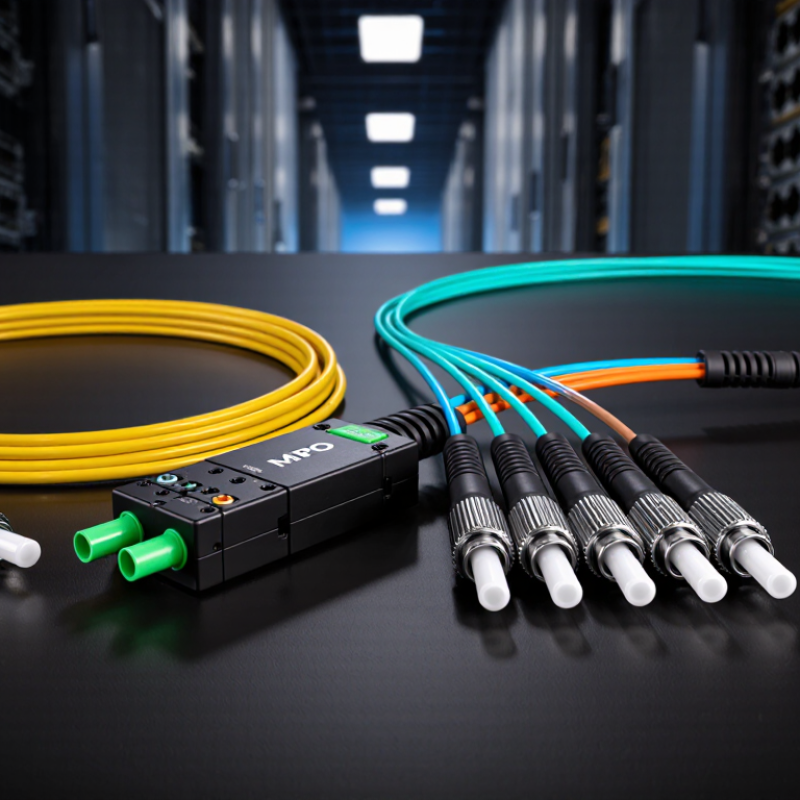
MPO Patch Cable Fundamentals: Multi-Fiber Ferrules Under IEC 61754-7
An MPO patch cable carries several optical fibers through one connector, rather than using a separate connector for each fiber. Its defining feature is the multi-fiber ferrule, a small rectangular component that holds fiber ends in precise rows. IEC 61754-7 specifies the MPO connector interface, including key features that support alignment and mating. The standard helps ensure compatible connections, but it does not guarantee that every cable performs equally well.
MPO cables come in different fiber counts, such as 8, 12, 16, or 24 fibers. They may also use pinned or unpinned connectors. Pins align mating ferrules, so a pinned connector must connect to an unpinned one. Polarity options determine how transmit and receive paths map between ends. This detail is easy to overlook. A mismatch can leave a link dark even when the connectors appear properly seated. Cable choice depends on the equipment, fiber count, and required polarity.
Tips: Check the connector gender and polarity before installation. Inspect and clean both end faces with suitable tools. A tiny speck can affect several channels at once. Verify the actual link with a test instrument; visual inspection alone is not enough. One practical caveat: documentation may not describe every cable detail, so confirm the configuration before ordering.
Fiber Counts Explained: 8, 12, 16, 24, and 32-Fiber MPO Configurations
An MPO patch cable carries multiple fibers in one compact connector, but the fiber count is not the same as transmission speed. The key detail is how many fibers the optics actually use. IEEE 802.3bm specifies 100GBASE-SR4 with four transmit and four receive fibers, so eight fibers carry the signal. A 12-fiber cable can support that link too, leaving four fibers unused in that connection. That matters.
Sixteen-fiber MPO configurations suit parallel links such as 400GBASE-SR8, which uses eight transmit and eight receive fibers, as specified in IEEE 802.3cm. Twenty-four-fiber trunks commonly combine two 12-fiber arrays, making them useful for connecting several links or breakout modules. Thirty-two-fiber designs commonly use two 16-fiber arrays, supporting dense cabling where space is tight. But the connector count alone does not define the application. Polarity, fiber type, transceiver design, and end-to-end mapping all matter. A small mismatch can leave a link dark. The standards describe the optical interfaces; installation plans still need careful checking.
MPO Polarity Types A, B, and C: How Each Maps Fiber Positions
MPO polarity describes how fibers travel from one connector end to the other. For a 12-fiber cable, Type A keeps positions straight: fiber 1 connects to fiber 1, and fiber 12 to fiber 12. The sequence does not reverse. This can look simple on a test sheet, but the connector’s key orientation matters when reading positions.
Type B reverses the full sequence. Fiber 1 connects to fiber 12, fiber 2 to fiber 11, and so on. Fiber 12 connects to fiber 1. This arrangement is commonly used when a link needs transmit and receive paths to cross between parallel-optics equipment. Check the system design rather than assuming a Type B cable fits every link.
Type C reverses fibers in adjacent pairs: 1 connects to 2, 2 to 1, 3 to 4, and 4 to 3. The same pattern continues through the row. A small label can save time. Before installation, confirm the polarity method at both ends and the intended viewing direction in the diagram. Drawings sometimes leave that detail unclear, and that is easy to overlook. A continuity test can verify the actual mapping before the cable is put into service.
MPO Cable Types by Fiber: OS2, OM3, OM4, and OM5
MPO patch cables can carry multiple fibers through one connector, but the fiber type still sets important limits. OS2 is single-mode fiber, commonly chosen for longer links between rooms or buildings. Its small core guides light over distance with less modal dispersion than multimode fiber.
That matters. Reach depends on the optics, link budget, and installation quality, not the cable label alone.
OM3 and OM4 are multimode fibers designed for high-speed links over shorter distances, often within data centers. OM4 generally supports greater reach than OM3 at the same application and wavelength. OM5 is also multimode, with a wider specified wavelength range that can support shortwave wavelength-division multiplexing.
The difference is useful only when the transceivers and system design support it. Details still matter. Check the equipment requirements before selecting an MPO cable, and confirm fiber grade, connector polish, polarity, and pin configuration.
A cable may look right and still fail to match the link. Real installations can also expose weak labeling or routing assumptions; documenting each connection helps, though it is easy to overlook during a quick upgrade.
Connector Options: Male or Female Pins, APC or UPC, and Loss Grades
MPO patch cables use a multi-fiber connector, so pin fit, polish, and insertion loss must all match. Male MPO connectors have guide pins; female connectors have alignment holes. A mating pair needs one of each. Two pinned ends cannot mate correctly, even if their housings appear compatible. The FOA Reference Guide to Fiber Optics explains the role of connector alignment in reducing signal loss. Check pin gender at both ends before ordering or connecting a cable.
APC and UPC describe end-face contact styles. APC uses an angled end face, commonly around 8 degrees, to reduce reflected light; UPC has a polished, near-flat contact. The choice should match the equipment and link design, not appearance alone. For loss grades, 0.75 dB and 0.35 dB are common maximum insertion-loss figures for standard- and low-loss MPO connections. They are not universal limits. TIA-568.3-E and IEC 61753-1 provide relevant cabling and connector-performance guidance, but confirm the supplier’s measured specification and test conditions. Small details matter.
Tips: Keep dust caps on until connection, and inspect both end faces before mating. A low-loss label does not guarantee a low-loss link; dirty interfaces, poor polarity, or mismatched pin gender can undermine the result. I would verify the test report, not rely on the label alone.
MPO Patch Cable Types: Connector Options and Loss Grades
Typical maximum insertion-loss limits for common MPO patch-cable specifications (dB). Actual limits vary by product and governing specification.
Connector options: Male MPO connectors have guide pins; female connectors do not. APC end faces are angled, while UPC end faces are flat. Use compatible pin, polish, and polarity configurations when connecting cables. Lower insertion loss means less optical power is lost at the connection.



 Find Your Solutions ▶