
What Is a MAG Welding Machine and How Does It Work?

A Mag Welding Machine feeds a continuous wire electrode into an electric arc while supplying an active shielding gas. The arc melts the wire and base metal, creating a joint as the molten pool cools. Its industrial relevance is substantial. Worldsteel’s World Steel in Figures 2024 reports global crude steel production of approximately 1.89 billion tonnes in 2023. That figure provides context for steel fabrication, although it does not measure MAG equipment demand.

MAG means metal active gas welding, a process within the broader gas metal arc welding family. Unlike MIG welding, MAG uses gases that influence arc behavior and weld chemistry, including carbon dioxide or argon-based mixtures. Gas selection matters. For example, an argon mixture containing 18% carbon dioxide is commonly used for welding carbon steel. A typical machine combines a power source, wire feeder, welding torch, and gas controls. Operators adjust voltage and wire feed speed to suit material thickness, joint geometry, and welding position.

Automation adds another reason to understand this equipment. The International Federation of Robotics’ World Robotics 2024 report recorded approximately 4.3 million industrial robots operating worldwide in 2023. These figures cover all industrial applications, so they should not be mistaken for welding-specific adoption data. Performance still needs scrutiny. A stable-looking arc can conceal inadequate fusion when settings, torch angle, or travel speed are unsuitable. This guide explains how MAG equipment works, where it fits, and which operating choices influence weld quality. Practical results depend on preparation and procedure, not simply the machine’s advertised output.
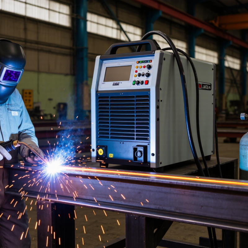
What Is a MAG Welding Machine and How Does It Work?

What Is a MAG Welding Machine?

A MAG welding machine is a power source and wire-feeding system used for metal active gas welding. It continuously feeds a consumable wire electrode through a torch, where an electric arc melts the wire and the workpiece. Shielding gas flows around the arc and molten pool, reducing exposure to air. MAG commonly uses carbon dioxide or an argon–carbon dioxide blend.

ISO 4063 identifies solid-wire MAG welding as process 135. The name is slightly confusing: MAG describes the shielding gas, not a special kind of metal.

In use, the operator sets voltage and wire-feed speed, then guides the torch along the joint. The gas composition, wire diameter, and travel speed affect arc stability, penetration, and spatter. A steady hand helps. So does clean metal.

Too much gas flow can create turbulence and disturb shielding; too little may leave the weld vulnerable to porosity. These details make setup and observation essential, not optional.

The American Welding Society’s 2023 workforce analysis projected that the United States would need about 330,000 new welding professionals by 2028, including replacements and additional workers. That figure is not specific to MAG welding, but it highlights why practical process knowledge matters.

A MAG machine can produce consistent welds, yet it does not correct poor fit-up or unsuitable settings. The operator still has to inspect the bead and adjust. Not magic.

Main Components and Their Functions

A MAG welding machine uses a continuous wire electrode and an active shielding gas to join metal. Its power source controls the welding current and voltage, which affect heat, penetration, and bead shape. Too much heat can burn through thin sheet; too little may leave a weak joint. Settings need to suit the material thickness and wire size.

The wire feeder pushes electrode wire through a cable to the welding torch. Inside the torch, the contact tip transfers current to the wire, while the nozzle directs shielding gas around the arc. The gas system typically includes a cylinder, regulator, and hose. Check the flow at the torch, not just the regulator. Small leaks or drafts can disrupt shielding and leave pores in the weld.

A work clamp completes the electrical circuit by connecting the workpiece to the machine. Controls let the operator adjust wire speed, voltage, and sometimes inductance or operating mode. The torch, feeder, and power source must work together; changing one setting can alter the arc’s sound and feel. It takes practice. Even a clean-looking bead may hide poor fusion, so inspect the joint and test settings on scrap of similar thickness.

What Is a MAG Welding Machine and How Does It Work? - Main Components and Their Functions

Component Main Function How It Works in MAG Welding Practical Notes
Power source Provides electrical power for the welding arc. In common wire-feed MAG systems, it supplies direct current and typically uses a constant-voltage output. The arc melts the continuously fed wire and part of the workpiece. Output settings must suit the material, wire diameter, joint, and welding procedure.
Wire feeder and drive rolls Feeds electrode wire from the spool to the welding torch. Motor-driven rolls push the wire through the torch liner. Wire-feed speed influences the rate at which wire enters the arc and is one of the main process settings. Rolls, liner, and contact tip should be suitable for the wire type and diameter to support smooth feeding.
Welding wire (consumable electrode) Conducts welding current and supplies filler metal. The wire travels through the torch, becomes electrically energized at the contact tip, and melts into the weld pool. Wire composition and diameter should be selected for the base material and welding requirements.
Welding torch and contact tip Guides the wire and delivers current to it. The contact tip transfers current to the moving wire. The torch also directs shielding gas toward the arc and weld pool. A worn or incorrectly sized contact tip can contribute to unstable feeding or an inconsistent arc.
Gas nozzle Directs shielding gas around the arc and weld area. Gas flows through the torch and exits the nozzle to help shield the molten metal from atmospheric contamination. Spatter or blockage inside the nozzle can disturb gas coverage.
Shielding-gas supply Protects the arc and molten weld pool from the surrounding air. MAG uses an active shielding gas, commonly carbon dioxide or an argon–carbon dioxide mixture. The gas can influence arc behavior, penetration, and spatter. Gas selection and flow should follow the applicable welding procedure and equipment guidance.
Gas regulator and flowmeter Reduces cylinder pressure and allows gas flow to be set and monitored. The regulator lowers the high pressure from the gas cylinder; the flowmeter indicates the gas flow supplied to the torch. Check connections for leaks and use a flow setting appropriate to the torch, nozzle, and working conditions.
Work lead and work clamp Completes the welding circuit through the workpiece. The clamp connects the workpiece to the power source return circuit, allowing current to flow through the arc and back to the machine. Attach it to clean, secure metal with good electrical contact.
Control panel Allows the operator to adjust and monitor welding settings. Depending on the machine, controls may include voltage, wire-feed speed, operating mode, and gas or wire-feed functions. Use settings specified by the welding procedure where one is available.

How MAG Welding Works Step by Step

A MAG welding machine joins metal with a continuously fed wire electrode and an electric arc. The process uses an active shielding gas, commonly a mixture containing argon and carbon dioxide. The gas flows around the arc and molten weld pool, helping protect them from air. The wire melts and becomes part of the joint.

Start by matching the wire and gas to the metal and its thickness. Connect the work clamp to clean metal, then check the torch, wire feed, and gas flow. Set voltage and wire speed according to the machine’s guidance.

A short test bead helps. Listen to the arc. A steady crackle can indicate a stable setup, though sound alone is not enough. Hold the torch at a consistent angle and move it evenly along the joint.

Press the trigger to feed wire and start the arc; keep the nozzle close enough for shielding gas to protect the pool. Watch the puddle’s edges as they fuse with the base metal.

If the bead looks uneven, pause and inspect your travel speed, settings, and surface preparation. Even experienced welders sometimes need another test.

Let the work cool, then check the bead for gaps, excessive spatter, or poor fusion.

Active Shielding Gases and Key Welding Settings

In MAG welding, shielding gas is an active part of the process, not just a barrier against air. Carbon dioxide can produce a forceful arc and deeper penetration, while argon-rich blends generally give a smoother arc and less spatter. The AWS Welding Handbook discusses these effects as practical trade-offs in gas metal arc welding. ISO 14175:2008 classifies argon mixtures containing 5–25% carbon dioxide as M21. That range is useful, but it does not identify one perfect mixture for every joint.

Settings must match the gas, wire, material thickness, and joint position. Wire-feed speed largely controls current; voltage influences arc length and bead shape. Travel speed then changes how much heat stays in the workpiece. For a small steel fillet, a shop might begin near 12–18 L/min of gas flow, then check coverage for drafts and nozzle distance. Too little flow invites porosity; too much can disturb the shielding. Small changes matter. A tidy chart can still mislead. AWS guidance supports testing settings on similar scrap, then inspecting the bead and weld root before production. I would not treat a stable-looking arc as proof of sound fusion.

What Is a MAG Welding Machine and How Does It Work?

MAG (Metal Active Gas) welding uses a wire electrode and an active shielding gas to protect the weld pool. This chart compares common shielding-gas mixtures by volume. Argon is the balance gas in the blends; carbon dioxide and oxygen are the active components.

Key settings: Voltage mainly affects arc length, while wire-feed speed strongly influences welding current. Choose these settings for the wire diameter, material thickness, joint, and transfer mode; then match the gas blend to the process and desired weld characteristics.

Suitable Materials, Common Uses, and Process Limitations

A MAG welding machine feeds a continuous wire electrode through a torch while shielding gas protects the molten weld pool. The gas is active, often carbon dioxide or an argon–carbon dioxide blend. This makes the process well suited to carbon steel and many low-alloy steels. Stainless steel can also be welded with suitable wire and gas, but settings and gas composition need careful selection. Fit matters.

MAG is common in vehicle repair, steel fabrication, machinery production, and workshop assembly. A steady wire feed suits long seams and repeated parts, such as brackets or frame joints. On a bench, a welder can often maintain a consistent bead at useful production speeds. Yet speed alone is not a quality check; joint preparation and operator technique still matter.

The process has limits. Wind can disturb shielding gas, so outdoor welds may become porous unless the work area is protected. Thin sheet can burn through, while poor settings may leave spatter around the bead. Rust, paint, oil, or mill scale can also undermine weld quality, even when the machine sounds steady. The name can mislead: MAG is not a universal metal process, and aluminum usually calls for inert-gas shielding. Real work is less tidy than a chart suggests.

Certified Quality System

© North Easton Machine Company, Inc. All rights reserved. • Site: Blog
NORTH EASTON MACHINE • 218 Elm Street • North Easton, MA 02356 • 508-238-6219