
What Are Electrical Diagnostic Tools Used For?
Electrical Diagnostic Tools help technicians find faults that are difficult to see directly. A digital multimeter can measure voltage, resistance, and continuity. A clamp meter checks current without disconnecting a conductor. Insulation testers assess whether insulation is leaking current, while thermal cameras reveal unusual heat around terminals, motors, and circuit breakers. Each tool answers a different question. None gives a complete diagnosis by itself.
In practice, these tools support troubleshooting in homes, workshops, vehicles, and industrial systems. A technician might compare readings across a circuit, inspect a warm connection, then consult the equipment’s wiring diagram. That evidence can distinguish a loose terminal from a failed component or an overloaded circuit. The details matter. A reading taken at the wrong point, with the wrong range, or using an unsuitable instrument can mislead. Even a clear display does not explain every cause.
Safe, reliable diagnosis depends on more than owning good equipment. Users should select instruments rated for the system, inspect leads and probes, and follow the manufacturer’s instructions. Circuits may need to be isolated before testing; only trained people should perform work that exposes hazardous live parts. Readings should be recorded and compared with specifications, not treated as guesses. Still, measurements have limits. Conditions change, and an intermittent fault may disappear during testing. Knowing what a tool cannot prove is part of using it well.
What Electrical Diagnostic Tools Measure and Analyze
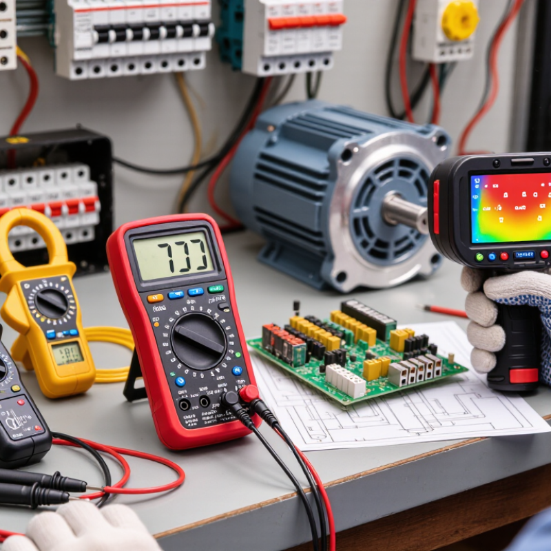
Electrical diagnostic tools measure the values that reveal how a circuit is behaving. A digital multimeter checks voltage, current, resistance, and continuity at specific test points. Its continuity tone can help locate a broken wire, but it cannot confirm that the connection will carry a working load. Small clues matter.
A clamp meter measures current around an insulated conductor, while an oscilloscope displays voltage changes over time. These readings can expose brief voltage drops, noisy signals, or irregular pulses that a single meter reading may miss. Capacitance and frequency functions help assess components such as capacitors and motor circuits against their stated specifications. Thermal imaging can show uneven heat across a panel, though a hot spot alone does not identify its cause.
Measurements need context. A low voltage reading might indicate a weak supply, a poor connection, or simply the wrong test point. Technicians compare results with circuit diagrams, equipment ratings, and readings from related points. They also check meter settings and probe contact; small setup errors can produce convincing but misleading numbers. A reading is evidence, not a diagnosis.

How These Tools Detect Faults in Electrical Circuits
Electrical diagnostic tools reveal problems that are difficult to see by eye. A digital multimeter measures voltage, resistance, and continuity at specific points. If a lamp stays dark, a technician can check whether voltage reaches its socket and whether the circuit path is complete. A clamp meter measures current around an insulated conductor, helping identify unexpected loads without disconnecting the wire. Small details matter. A loose probe or corroded contact can distort a reading, so measurements should be checked against the circuit’s design.
Other tools help narrow down less obvious faults. An insulation tester applies a controlled test voltage to an isolated circuit and checks for current leaking through damaged insulation. It must not be used carelessly on connected electronics. A thermal camera can reveal an unusually warm terminal or breaker, which may point to a poor connection or overload. Heat is a clue, not proof. Technicians compare readings at several points, inspect the circuit, and repeat tests when results seem inconsistent. Electrical testing can be hazardous; live measurements should be performed only by qualified people using suitable protective equipment. Even then, one puzzling reading may need a second look.
How Electrical Diagnostic Tools Detect Circuit Faults
Voltage-drop testing compares the voltage across circuit connections while current is flowing. An unusually high drop can reveal excess resistance, such as a loose or corroded connection.
Illustrative readings for a 12 V DC circuit under a 10 A load. Actual readings vary by circuit and test conditions; the elevated switch-contact drop represents a possible high-resistance fault.
Which Instruments Test Voltage, Current, and Resistance
Electrical diagnostic tools help locate faults by measuring voltage, current, and resistance. A digital multimeter can test all three, provided its selector and lead sockets match the measurement. To check voltage, place the probes across the two points being tested, using the correct AC or DC setting. A non-contact voltage tester can indicate nearby energized wiring, but it cannot confirm that a circuit is safe to touch. Useful, but limited.
Current measurements need a different approach. A clamp meter reads current around a single conductor without disconnecting it; clamping around an entire cable may cancel the reading. A multimeter can measure current in series, but the circuit must be connected through the meter’s correct input. This setup is easy to get wrong, so pause and check the manual.
For resistance, switch off power and verify the circuit is de-energized before placing probes across the component. Resistance readings on live circuits can damage the meter and mislead the diagnosis. That distinction matters. Inspect leads for cracked insulation, select equipment rated for the circuit, and treat an unexpected reading as a reason to check connections and test conditions.
How Diagnostic Tools Help Verify Electrical Safety
What Are Electrical Diagnostic Tools Used For?
How Diagnostic Tools Help Verify Electrical Safety
Electrical diagnostic tools help technicians check whether wiring and equipment behave as expected. A properly rated multimeter can measure voltage, resistance, and continuity. Insulation resistance testers can reveal weakened insulation, while clamp meters measure current without disconnecting conductors. Each tool answers a different question. None can confirm every aspect of safety alone.
Before work begins, a qualified person may use an approved voltage tester to check for hazardous voltage. The tester should be verified on a known live source before and after the check. A non-contact detector can help locate voltage, but it should not be the sole proof that a circuit is de-energized. Small details matter: damaged leads or the wrong meter setting can produce misleading results.
Tools also help assess protective paths, insulation condition, and whether equipment draws unusual current. Measurements need context, including the circuit design and the instrument’s rating. Testing should follow safe work procedures and the tool maker’s instructions. A reading can look reassuring and still miss a hidden fault. That is worth remembering. Regular calibration and careful recording make results more dependable, though even careful testing cannot replace sound judgment.
| Diagnostic tool | What it measures or checks | How it helps verify electrical safety | Important use notes |
|---|---|---|---|
| Digital multimeter | Voltage, resistance, and—when configured correctly—current and continuity. | Can help identify unexpected voltage, open circuits, and wiring or component faults. | Select the correct function and input terminals. Never measure resistance on an energized circuit; follow the meter’s ratings and instructions. |
| Two-pole voltage tester | Presence or absence of voltage between two points. | Helps confirm whether a circuit is energized before work begins. | Prove the tester on a known live source before and after checking the circuit. A zero reading alone does not prove a safe work condition. |
| Non-contact voltage detector | Detects an electric field near an energized conductor. | Provides a quick preliminary indication that voltage may be present. | It can miss voltage or respond to nearby energized wiring. Do not use it as the sole method to confirm a circuit is de-energized. |
| Insulation resistance tester | Insulation resistance between conductors or between a conductor and earth, using a test voltage. | Can reveal deteriorated, damp, or damaged insulation that may create shock or leakage-current risks. | Isolate the equipment and disconnect sensitive electronic devices before testing. Use the test voltage and acceptance criteria specified for the equipment. |
| Earth-fault loop impedance tester | Impedance of the fault-current path in an installation. | Helps assess whether a fault could produce enough current for the protective device to disconnect within the required time. | Testing should be performed by a qualified person using procedures appropriate to the installation and local electrical requirements. |
| RCD/GFCI tester | Operation and, on suitable instruments, trip time or trip current of a residual-current protective device. | Checks whether the device responds to a simulated leakage-current condition. | A test-button check is not a substitute for instrument testing where that is required. Follow the device and installation test instructions. |
| Clamp meter | Current flowing through a conductor, measured without disconnecting it. | Can help identify abnormal current, load imbalance, or current that may indicate a fault. | Clamp around one conductor for an individual circuit reading. Use a meter and accessories rated for the circuit’s voltage and environment. |
| Thermal imaging camera | Surface temperature patterns on electrical equipment. | Can help locate overheating connections, overloaded components, or uneven loading before a failure occurs. | Thermal images indicate temperature differences, not the cause of a fault. Interpret results alongside load conditions and inspection findings. |
| Continuity tester | Whether a low-resistance electrical path exists between two points. | Can help check protective conductors, bonding connections, and de-energized wiring paths. | Use only on isolated, de-energized circuits. Continuity alone does not confirm that a connection can safely carry fault current. |
Where Electrical Diagnostic Tools Are Commonly Used
What Are Electrical Diagnostic Tools Used For?
Where Electrical Diagnostic Tools Are Commonly Used
Electrical diagnostic tools are used wherever people need to locate faults, confirm circuit conditions, or check equipment performance. In homes, electricians may use a multimeter to investigate a dead outlet or a clamp meter to measure current without disconnecting a conductor. A non-contact voltage tester can help identify possible live wires, but it should not be treated as proof that a circuit is safe.
These tools also appear in commercial buildings and industrial facilities. Technicians may test motors, control panels, lighting circuits, and heating or cooling equipment. An insulation tester can help assess cable insulation, while a thermal camera may reveal a hot connection inside a loaded panel. Small clues matter. A warm terminal deserves attention, though temperature alone does not identify the cause.
On construction sites, diagnostic checks help confirm wiring and equipment before systems are put into service. Vehicle repair shops use electrical meters to trace battery, charging, and sensor problems. Maintenance teams in workshops and factories use them during routine inspections and fault finding. Real jobs are rarely tidy; readings can vary with load, access, and instrument setup. Trained users follow the tool’s rating and safety procedures, verify instruments before testing, and isolate power when the task requires it. A reading is useful, but context matters.
Article Source:
NORTH EASTON MACHINE • 218 Elm Street • North Easton, MA 02356 • 508-238-6219