How to Choose the Right M8 Pico Connector?
Choosing the right M8 Pico Connector starts with the equipment it must serve. These compact circular connectors often appear on sensors, actuators, and automation devices where space is limited. The familiar M8 threaded coupling helps secure a connection, but size alone does not determine compatibility. Check the pin count, contact arrangement, and coding against the device documentation. One mismatch can leave a carefully installed cable unusable.
Then consider the working environment. Will the connector face washdown, vibration, dust, oil, or repeated movement? Confirm the protection rating for the complete mated connection, not just one connector half. Review voltage and current limits, operating temperature, cable jacket material, and expected mating cycles. A PUR cable may suit demanding movement, while PVC may be adequate for a more static installation. Details matter.
Installation also shapes the choice. A straight connector may fit an open panel; an angled version can help where clearance is tight. Decide whether you need a field-wireable plug, a molded cable assembly, or a panel-mount receptacle. Compare the manufacturer’s drawings and datasheets, including thread dimensions and wiring diagrams, before ordering. Ask the supplier when ratings or compatibility are unclear. It is easy to focus on one attractive specification and miss a practical constraint. I would check the actual routing space twice; drawings rarely show every awkward bend. A well-chosen M8 Pico Connector should match the electrical interface, installation conditions, and maintenance plan—not merely the machine’s connector size.
Identify the Application and Operating Requirements
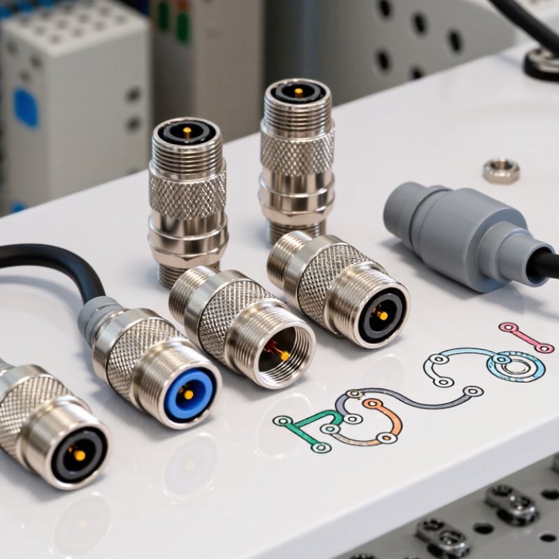
An M8 Pico connector should match the job, not just the sensor. Start by listing the connected device, signal type, pin count, and available space. Check whether the cable will face repeated bending, vibration, oil, dust, or washdown. A connector beside a moving machine arm may need a flexible cable and strain relief; a sheltered cabinet connection may not. Small details matter. IEC 61076-2-104 covers M8 circular connectors, while IEC 60529 defines IP enclosure ratings. Confirm the rating for the assembled connection, not only the connector body.
Next, compare the site’s operating limits with the connector and cable specifications. Check temperature range, voltage, current, mating cycles, and whether straight or angled exits suit the installation. The International Federation of Robotics reported 4.28 million industrial robots operating worldwide in 2023, up 10% from 2022. This scale highlights how many connections may face motion and vibration, though it does not mean every M8 installation needs the same protection. Inspect the actual route and service conditions. A rating on paper can be easy to misread.
Tips: Photograph the mounting point, measure clearance, and note nearby heat or spray. Verify pin assignment before ordering. If the duty cycle is uncertain, record that uncertainty and test a sample under realistic movement; this step is often overlooked.
Select the M8 Connector Configuration and Pin Arrangement
Choose an M8 connector by matching its configuration to the device and cable route. A straight version suits an open run, while an angled version can reduce strain where a cable exits near a panel or bracket. Check the available clearance before ordering; a connector that fits electrically may still hit a nearby enclosure. Small details matter.
Pin count should follow the actual circuit requirements, not guesswork. Three- and four-contact arrangements are common, but functions can vary by device. One contact may carry supply voltage, another the return, and others signal outputs; confirm each assignment in the equipment documentation. Do not assume that matching pin counts mean matching wiring. They may not. Compare the connector’s pin numbering, viewed from the correct mating side, with the cable diagram. A mirrored view can make a sound wiring plan look wrong—or worse, seem right.
Also verify gender, keying or coding, and the mating connector before installation. For a tight sensor mounting point, mark the cable’s bend direction and leave enough room to turn the coupling nut by hand. A useful habit is to label both ends of the cable before routing it. Pin maps can be easy to overlook during a rushed replacement, and that is one mistake worth catching early.
Compare Electrical Ratings and Signal Requirements
Treat M8 as a connector size, not an electrical specification. IEC 61076-2-104:2014 covers the M8 interface and test requirements, but allowable current and voltage depend on the specific assembly. Check the datasheet at your operating temperature, then compare its ratings with the sensor’s supply voltage, peak load, and cable length. For example, a 24 V sensor that switches a small valve may need more current margin than a low-power proximity sensor. Leave room for startup current. Small detail, big consequence.
Signal needs matter just as much. A discrete on/off signal is less demanding than an analog measurement or Ethernet link. IEC 61156-5:2020 specifies Category 6 balanced cable performance up to 250 MHz; that figure describes the cable, not an M8 connector automatically. For data links, verify coding, pin assignment, shielding, impedance, and the qualified channel performance. More pins do not guarantee cleaner signals. This is an easy point to misjudge. Compare the complete connector-and-cable assembly against the signal requirement, and check whether nearby motors or long cable runs could add noise. I would not treat a catalog headline rating as proof of suitability.
Check Environmental Protection and Material Options
Choosing an M8 pico connector means checking its complete operating environment, not just its IP label. IEC 60529 defines IP67 as dust-tight and suitable for temporary immersion at 1 m for 30 minutes. IP68 conditions depend on the manufacturer’s stated test conditions. These ratings describe controlled tests, not every installation. A cable bend, loose coupling nut, or damaged seal can still create a leak. Small details matter.
Check whether the rating applies when connectors are mated, unmated, or fitted with a protective cap. For washdown or outdoor exposure, compare the expected water pressure, temperature, vibration, and cleaning chemicals with the product specification. Nickel-plated brass can offer a durable housing; stainless steel may suit corrosive settings. Contact alloys and plating affect electrical performance, while PUR and PVC cable jackets differ in flexibility and chemical resistance. Verify each material against the actual fluid and temperature. Material names alone are not enough.
Tips: Request the IEC 60529 test conditions and material datasheets. Inspect seals after repeated mating. I would not assume an IP rating covers a connector left open in the field.
Verify Compatibility, Mounting, and Cable Requirements
How to Choose the Right M8 Pico Connector?
Verify Compatibility, Mounting, and Cable Requirements
Start by checking the connector’s pin count, coding, and mating interface against your equipment. Two M8 connectors can look almost identical but still fail to mate. Compare the pin layout and key position with the device documentation, not just the product photo. Also confirm whether you need a straight or angled connector. Small details matter.
Next, check how the connector mounts and where the cable will run. Measure the panel opening and available clearance around the connection. A threaded mount may need room for a nut and tool access. Match the cable’s length, conductor size, jacket material, and flexibility to the installation. For moving equipment, a stiff cable can pull at the connector over time. Check the required environmental rating, too; sealing performance can depend on correct assembly and a fully mated connection. It’s easy to overlook that.
Tips: Before ordering, sketch the connector’s orientation and cable route. Confirm the pinout from a reliable datasheet, then inspect the finished assembly for strain or tight bends. Leave a little room for adjustment.
| How to Choose the Right M8 Pico Connector? - Verify Compatibility, Mounting, and Cable Requirements | ||
|---|---|---|
| Selection Dimension | What to Verify | Practical Guidance |
| Thread and interface | Check the connector’s coupling thread and the mating part’s specification. | M8 connectors commonly use an M8 × 1 threaded interface: 8 mm nominal thread diameter and 1 mm pitch. Confirm the exact thread and applicable connector drawing before ordering. |
| Coding | Match the keying or coding on both connector halves. | A-coded M8 connectors are widely used for sensor and actuator connections. Other codings may also exist; connectors with different coding should not be assumed to mate or share the same pin arrangement. |
| Pin count and wiring | Confirm the number of contacts and each contact’s assigned function. | M8 connector families are available in several pin counts, including 3-, 4-, 5-, 6-, and 8-pin versions. Pin assignments can vary by device and application, so check the wiring diagram rather than relying on pin count alone. |
| Contact gender | Match pin contacts to socket contacts and check the connector’s gender description. | Product descriptions may specify contact gender separately from housing or cable-end gender. Compare the contact layout and mating drawing to avoid ordering two incompatible halves. |
| Mounting style | Choose between cable-mounted, panel-mounted, and field-wireable versions. | For panel mounting, verify front- or rear-mount installation, available space, thread engagement, sealing hardware, and the panel cutout dimensions in the product drawing. Cutout requirements are not universal. |
| Connector orientation | Check whether a straight or right-angle cable exit fits the installation. | A straight connector needs clearance behind the connection point. A right-angle version can help in confined spaces, but confirm its orientation and cable-exit direction against the equipment layout. |
| Voltage and current | Compare the connector ratings with the equipment’s operating and peak requirements. | Voltage and current ratings depend on the specific connector, contact count, wire size, and operating conditions. Use the component datasheet and allow for the limits of the complete connection. |
| Ingress protection | Verify the required IP rating for the actual installation. | Some M8 assemblies are rated IP67, but this rating applies only to products specifically tested or rated for it and only when installed and mated as specified, with seals in good condition. |
| Cable material and environment | Check temperature range, chemical exposure, abrasion, oil, and motion requirements. | PVC-jacketed cables are commonly used in general installations; PUR-jacketed cables are often selected for greater abrasion or oil resistance. Actual performance varies, so verify the cable’s stated environmental ratings. |
| Cable length and flexibility | Measure the required route and consider movement, routing, and voltage drop. | Select enough length to avoid tension and sharp bends. For moving installations, confirm the cable is rated for the required flexing or torsion and follow the manufacturer’s minimum bend-radius specification. |
| Shielding and grounding | Determine whether the application needs a shielded cable and how the shield must be terminated. | Shielding may help with electromagnetic interference in some installations, but it must be compatible with the equipment’s grounding and EMC requirements. Check the system wiring documentation. |
| Final check: Compare the connector drawing, coding, contact layout, mounting dimensions, cable specification, and electrical ratings for both mating parts before purchase or installation. | ||
Article Source:
NORTH EASTON MACHINE • 218 Elm Street • North Easton, MA 02356 • 508-238-6219