
How to Choose the Right Electro-Hydraulic Valve?
Choosing the right Electro-Hydraulic Valve can determine whether a machine responds smoothly or struggles under pressure. In real applications, small selection errors often become expensive maintenance problems. A valve may look suitable on paper, yet perform poorly beside heat, vibration, contaminated oil, or rapid load changes. The correct choice begins with the machine’s actual working conditions, not only its catalog rating.
This guide examines flow capacity, pressure range, response time, control signal, leakage, and installation requirements. It also considers spool design, material quality, sealing performance, and compatibility with the hydraulic fluid. A valve controlling a robotic arm needs different behavior from one operating a press. Measure the system carefully. Record peak pressure, normal flow, cycle frequency, and ambient temperature before comparing models. These details reveal practical risks that product brochures may hide.
Experience also teaches caution. A larger valve is not automatically better. Oversizing can reduce control sensitivity, while an undersized valve may generate heat and pressure loss. Manufacturer documentation, testing records, maintenance guidance, and recognized hydraulic safety practices deserve close attention. However, no selection method is perfect. Field conditions change, specifications may be incomplete, and installation quality can weaken excellent equipment. That uncertainty should remain visible. Engineers should verify assumptions through simulation, bench testing, and controlled commissioning whenever possible. The goal is not merely to purchase an Electro-Hydraulic Valve, but to create a stable, efficient, and serviceable hydraulic system.
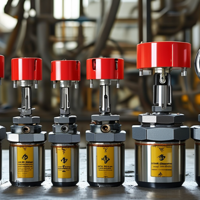
Define the Application Requirements and Operating Conditions
Choosing an electro-hydraulic valve begins with the application, not the catalog. Define required flow, pressure, response time, duty cycle, and actuator load. A valve rated for 250 bar may perform poorly if pressure spikes occur repeatedly. Record peak pressure, return-line pressure, oil temperature, and expected cycle frequency.
Keep measurements realistic. A 10% flow margin is often useful, but excessive oversizing can reduce control resolution. According to the 2024 NFPA Fluid Power Economic Outlook, industrial fluid-power demand remains closely tied to manufacturing output and equipment investment. That connection matters: production lines usually punish slow response and unplanned maintenance. For precision motion, specify allowable drift, hysteresis, and repeatability. For simple directional control, those requirements may be unnecessary.
Oil condition deserves equal attention. The ISO 4406 cleanliness code provides a practical method for defining particle contamination levels. A 2023 technical report from the International Council for Machinery Lubrication notes that contamination remains a major contributor to hydraulic component wear. Clean oil helps, but it does not solve poor filtration design. Check filter location, bypass settings, water exposure, and seal compatibility. Environmental temperature changes can also alter viscosity and response.
Do not ignore installation details. Long hoses add delay. Trapped air creates unstable movement. Electrical noise can disturb command signals. I have seen specifications focus on pressure while overlooking cable routing and grounding. That mistake is easy to repeat. Test the valve under actual load, not only on a bench. Record cold-start behavior, thermal performance, leakage, and emergency-stop response before final selection.
How to Choose the Right Electro-Hydraulic Valve? — Define the Application Requirements and Operating Conditions
Use the following application and operating-condition checklist to match an electro-hydraulic valve with the required flow, pressure, control method, environment, and safety needs.
| Requirement Dimension | Typical Application Data | Why It Matters | Recommended Valve Consideration | Example Selection Guidance | Check |
|---|---|---|---|---|---|
| Actuator Type | Hydraulic cylinder, hydraulic motor, or rotary actuator | The actuator determines the required flow direction, metering method, and port arrangement. | Select a directional valve for cylinder movement or a suitable pressure-compensated flow-control arrangement for motor speed regulation. | Double-acting cylinder: typically use a 4/3 or 4/2 directional control valve. | Define first |
| Required Flow Rate | 5–120 L/min, depending on actuator speed and system demand | Flow capacity affects actuator velocity, pressure drop, heat generation, and response time. | Choose a valve with a rated flow above the maximum continuous operating flow while checking the manufacturer’s pressure-drop curve. | For a 50 L/min system, select a valve rated for approximately 60 L/min or more if transient demand is expected. | Size with margin |
| Operating Pressure | 70–250 bar in many industrial systems | The valve must withstand normal pressure, peak pressure, and pressure spikes without leakage or structural damage. | Verify both the maximum rated pressure and the allowable pressure at each port. Do not size only from normal working pressure. | For a 210 bar working system with possible spikes, use a valve rated above the expected peak pressure. | Check peaks |
| Pressure Drop | Application-dependent; often targeted below 5–10 bar across the valve | Excessive pressure drop wastes energy, raises fluid temperature, and reduces available actuator force. | Compare pressure-drop data at the actual operating flow rather than relying only on nominal port size. | For energy-sensitive equipment, favor a larger nominal valve size if it lowers pressure loss at peak flow. | Review curve |
| Control Accuracy | Basic on/off, proportional control, or closed-loop position/velocity control | Control accuracy determines whether a simple solenoid valve is sufficient or whether feedback and fine metering are required. | Use directional solenoid control for binary motion; use proportional or servo-type control for adjustable speed, position, or force. | Material-handling positioning generally requires proportional control or an external feedback loop. | Match precision |
| Response Time | Approximately 20–100 ms for many fast industrial control tasks | Slow response can cause positioning errors, cycle-time losses, or unstable control behavior. | Check electrical switching time, spool dynamics, pilot-stage behavior, and hydraulic response under the actual load. | High-speed motion control may require a proportional valve with a dedicated amplifier and suitable feedback. | Test dynamically |
| Electrical Supply | Common control supplies include 12 VDC, 24 VDC, and 110/230 VAC | Voltage, current, connector type, and signal compatibility affect installation and reliable valve actuation. | Confirm coil voltage, power consumption, control signal type, duty rating, polarity requirements, and connector protection. | For automated machinery, 24 VDC is widely used because it integrates easily with industrial control systems. | Verify interface |
| Control Signal | On/off, 0–10 V, ±10 V, 4–20 mA, or fieldbus command | The valve input must be compatible with the controller and signal wiring to avoid inaccurate or unavailable control. | For analog signals, assess resolution, noise immunity, ramp control, and command-to-flow linearity. | Use 4–20 mA for long cable runs where improved noise resistance and fault detection are beneficial. | Match controller |
| Spool and Center Function | Closed center, open center, tandem center, or float center | The center condition determines pump unloading, actuator holding, pressure behavior, and fail-state movement. | Select the center configuration according to the hydraulic circuit and the required behavior when the valve is de-energized. | Closed-center circuits can hold actuator pressure but may require a pressure-compensated pump or unloading strategy. | Circuit critical |
| Fail-Safe Behavior | Hold position, return to neutral, retract, extend, or depressurize | Loss of power or control signal can create personnel, equipment, or process hazards. | Define the safe state before selecting spring return, detent, pilot operation, counterbalance, or load-holding components. | Vertical loads often require load-holding protection in addition to the valve’s normal center position. | Safety review |
| Fluid Type | Mineral hydraulic oil, water-glycol, or biodegradable hydraulic fluid | Fluid chemistry affects seal compatibility, lubrication, corrosion resistance, and service life. | Confirm compatibility of seals, coatings, internal materials, and electrical components with the selected fluid. | Water-based fluids may require special materials and can reduce lubrication compared with mineral oil. | Confirm materials |
| Fluid Temperature | Typical operating range: approximately 0–80°C; application limits vary | Temperature changes viscosity, leakage, response, seal life, and electrical coil performance. | Check the valve’s fluid-temperature range and ensure viscosity remains within the recommended operating window. | Cold starts may require low-temperature fluid selection or preheating to prevent sluggish operation. | Check viscosity |
| Ambient Environment | Indoor, outdoor, dusty, wet, corrosive, or hazardous area | Moisture, dust, chemicals, and explosive atmospheres influence enclosure, coating, and certification requirements. | Specify an appropriate ingress-protection level, corrosion-resistant finish, connector sealing, and hazardous-area approval where required. | Outdoor equipment commonly requires sealed electrical connections and protection against condensation and corrosion. | Assess exposure |
| Installation Space | Subplate, manifold, inline, or compact integrated assembly | Physical constraints affect port orientation, maintenance access, heat dissipation, and replacement time. | Choose the mounting standard, port size, envelope dimensions, and service clearance before finalizing the valve. | Manifold mounting can reduce tubing and leakage points but requires accurate interface dimensions. | Confirm layout |
| Contamination Level | Clean, controlled industrial fluid or contamination-prone mobile environment | Particles can cause spool sticking, erosion, leakage, and premature failure. | Specify suitable filtration, cleanliness targets, and contamination-tolerant design; maintain the fluid according to system requirements. | A fine return-line or pressure-line filter may be needed for precision proportional control, subject to circuit design. | Plan filtration |
| Duty Cycle | Intermittent operation, repeated cycling, or continuous energized operation | Duty cycle affects coil heating, seal wear, thermal limits, and expected service life. | Verify continuous-duty capability, maximum switching frequency, thermal dissipation, and rated cycle life. | For continuous energization, use a coil and valve configuration specifically rated for continuous duty. | Check thermal load |
| Noise and Efficiency | Low-noise factory, mobile machinery, or standard industrial environment | Throttling losses, turbulence, cavitation, and solenoid noise can affect operator comfort and energy consumption. | Optimize valve sizing, avoid excessive pressure drop, and check for cavitation risk at restricted outlets or return lines. | Use appropriate orifice sizing and pressure-compensated control where stable flow is needed across changing loads. | Optimize system |
| Maintenance and Diagnostics | Manual service, condition monitoring, or remote maintenance | Accessible diagnostics reduce downtime and help identify electrical, hydraulic, and contamination-related faults. | Consider spool-position feedback, pressure sensors, indicator lights, manual override access, and replaceable wear components. | Critical automated equipment benefits from electrical status feedback and pressure monitoring at key ports. | Plan service |

Certified Quality System

 Find Your Solutions ▶
NORTH EASTON MACHINE • 218 Elm Street • North Easton, MA 02356 • 508-238-6219